Setup steps
This section provides recommended steps to set up Oracle SOA Suite enterprise deployment on Kubernetes to eliminate single points of failure and to provide high availability.
- Set up your Kubernetes cluster
- Prepare the environment
- Create a database and the appropriate database services
- Install and configure Oracle HTTP Server in the DMZ
- Configure a front-end load balancer
- Create worker nodes
- Apply operating system changes for Coherence
- Deploy WebLogic Kubernetes Operator and Oracle SOA Suite
- Configure redundant persistent volume
- Configure the required priority for mounts
- Set front-end addresses
- Enable FAN for GridLink data sources
- Configure ASM
- Configure coredns allocation
- Adjust server’s pods Liveness Probe
Set up your Kubernetes cluster
Prepare the environment for the Kubernetes control plane (Master nodes)
-
Create the L4/TCP listener for the load balancer (LBR).
-
Create the LBR backend pool with the list of control plane nodes that will be added (do not use IPs, always use hostnames).
Note: We recommend maintaining the values of the following
kube-apibackend pool parameters within the prescribed range to minimize the downtime while restarting the Kubernetes control pane or performing maintenance operations.- Healthcheck interval : Within 1000 milliseconds
- Healthcheck timeout : Within 900 milliseconds
-
Enable the L4 LBR to route to the backend set/pool.
Note: It is important that this is an L4/TCP listener, not an HTTP/HTTPS listener.
-
Make sure that the nodes are in ready state.
-
Create an ssh key (use a common ssh key to enable access from the node executing the setup to the control plane nodes).
-
Allow traffic in intermediate firewalls between control plane nodes and the front-end LBR. Refer to the Kubernetes documentation for the required ports.
Set up Master nodes
Refer to the README to set up the master nodes.
Note: It is recommended to set up the control plane (Master) with three nodes. See the Topology for more details.
Prepare the environment
Configure firewalls and network
- Allow traffic from the load balancer (LBR) to the Oracle HTTP Server (OHS) port that will be configured (7777 by default for OHS).
- Allow traffic from the OHS to the node port that will be configured in the worker nodes for the Administration Server (30701), SOA cluster (30801), and Service Bus cluster (30901).
- Allow traffic from the worker nodes to the control plane front-end
kube-apivirtual server port and also to the front-end Oracle SOA Suite. - Allow traffic from worker nodes to the database listener and ONS port (1521 and 6200 by default, respectively).
You can use the Enterprise Deployment Guide for Oracle SOA Suite on-premise as a reference.
Load Oracle SOA Suite images on all the worker nodes
Refer to Obtain the Oracle SOA Suite Docker image to load the images on each worker node and tag appropriately.
Enable a shared storage location for the persistent volume
A shared storage device must be used from the different worker nodes. This storage hosts the Oracle SOA Suite domain directory. Initially, a single storage location is used to create a persistent volume that will host the Oracle SOA Suite domain. Mount this shared storage (NFS/NAS) from all the worker nodes using the same mount path in all of them.
For example, mount NFS1 (10.10.0.21:/k8nfs) in all the worker nodes to a share directory /k8nfs:
$ grep "k8nfs nfs"  /etc/fstab
10.10.0.21:/k8nfs /k8nfs nfs rw,relatime,vers=3,rsize=1048576,wsize=1048576,namlen=255,hard,proto=tcp,timeo=600,retrans=2,sec=sys,mountaddr=10.10.0.21,mountvers=3,mountport=2048,mountproto=udp,local_lock=none,addr=10.10.0.21
Later, steps are provided to configure a second storage location for high availability.
Create a database and the appropriate database services
The installation and creation of the RAC database is out of the scope of this document. Once the database is configured, the appropriate services must be created to access the schemas from the middle tier. It is critical that a precise non-default/administration service is created for Oracle SOA Suite. Refer to Preparing the Database for an Enterprise Deployment in the Enterprise Deployment Guide for Oracle SOA Suite 12.2.1.4.
Install and configure Oracle HTTP Server in the DMZ
Follow the steps in the Enterprise Deployment Guide for Oracle SOA Suite to create two Oracle HTTP Server (OHS) instances in separate nodes from the worker nodes. To configure OHS with the back-end Kubernetes Oracle SOA Suite or Service Bus servers, you must use a port in the range of 30000 - 32767. You will use this port in the Oracle SOA Suite configuration scripts later on.
- Configuring Oracle HTTP Server to Route Requests to the Administration Server URL and WSMPM
- Configuring the Web Tier for the Oracle SOA Extended Domain
- Configuring the Web Tier for the Oracle Service Bus Extended Domain
In this Kubernetes Enterprise Deployment Guide, OHS routes to node ports configured for each separate Oracle SOA Suite/Service Bus cluster in the SOA domain. OHS then routes to these node ports, which redirect to the pertaining server pods. The OHS directive for the configuration must disable DynamicServerList because the node ports are not really WebLogic listeners and it is the node port configuration that maintains an intelligent list of available WebLogic servers. The OHS directive for the soa-infra mount in OHS looks like this:
<Location /soa-infra>
  WLSRequest ON
  DynamicServerList OFF
  WebLogicCluster workernode1:30801,workernode2:30801,workernode3:30801
  WLProxySSL OFF
  WLProxySSLPassThrough OFF
</Location>
Similarly, the other directives for other paths should reflect similar node port addresses.
Configure a front-end load balancer
You can either use BigIp F5 LBR or any standard LBR, such as CISCO. Refer to the Enterprise Deployment Guide for Oracle SOA Suite for the required virtual servers: Preparing the Load Balancer and Firewalls for an Enterprise Deployment. The on-premises Enterprise Deployment Guide provides a detailed list of virtual servers/listeners that can be used for optimum isolation of services and traffic. For Kubernetes, at a minimum you should have a virtual server/listener for Oracle SOA Suite using the OHS listeners as back-end pool.
-
Create the load balancer’s L7/http listener.
-
Create a back-end pool with the list of OHS nodes/ports that will be used by Oracle SOA Suite (do not use IPs, always use hostnames).
-
Enable the L7/http listener load balancer to route to the OHS back-end set/pool.
-
Configure the front-end load balancer to route to the OHS pool.
Create worker nodes
Refer to Set up Worker nodes for details.
Apply operating system changes for Coherence
Coherence requires specific settings to create clusters in a Kubernetes environment. Refer to the steps provided in the WebLogic Kubernetes Operator documentation.
Deploy WebLogic Kubernetes Operator and Oracle SOA Suite
The steps to deploy WebLogic Kubernetes Operator and the Oracle SOA Suite domain are automated with the scripts. Refer to the README for details.
After successful Oracle SOA Suite domain creation and starting the servers, check the pods and the different services created. Once the Oracle SOA Suite managed servers reach RUNNING state (the pods are ready), check typical Oracle SOA Suite URLs using the front-end load balancer:
SOA pods and services deployed and ready:
$ kubectl get all -n soans
NAME                                                 READY   STATUS      RESTARTS   AGE
pod/soaedgdomain-adminserver                         1/1     Running     0          47h
pod/soaedgdomain-create-soa-infra-domain-job-6pq9z   0/1     Completed   0          68d
pod/soaedgdomain-soa-server1                         1/1     Running     0          2d2h
pod/soaedgdomain-soa-server2                         1/1     Running     0          2d2h

NAME                                                 TYPE        CLUSTER-IP       EXTERNAL-IP   PORT(S)                          AGE
service/soaedgdomain-adminserver                     ClusterIP   None             <none>        30012/TCP,7001/TCP               2d4h
service/soaedgdomain-adminserver-ext                 NodePort    10.104.20.22     <none>        30012:30012/TCP,7001:30701/TCP   31d
service/soaedgdomain-cluster-osb-cluster             ClusterIP   10.100.97.127    <none>        8002/TCP                         68d
service/soaedgdomain-cluster-soa-cluster             ClusterIP   10.101.101.113   <none>        7003/TCP                         68d
service/soaedgdomain-cluster-soa-cluster-node-port   NodePort    10.105.51.223    <none>        7003:30801/TCP                   68d
service/soaedgdomain-osb-server1                     ClusterIP   10.110.81.153    <none>        8002/TCP                         2d4h
service/soaedgdomain-osb-server2                     ClusterIP   10.103.220.112   <none>        8002/TCP                         2d4h
service/soaedgdomain-osb-server3                     ClusterIP   10.97.50.117     <none>        8002/TCP                         2d4h
service/soaedgdomain-osb-server4                     ClusterIP   10.98.48.247     <none>        8002/TCP                         2d4h
service/soaedgdomain-osb-server5                     ClusterIP   10.102.137.176   <none>        8002/TCP                         2d4h
service/soaedgdomain-soa-server1                     ClusterIP   None             <none>        7003/TCP                         2d4h
service/soaedgdomain-soa-server2                     ClusterIP   None             <none>        7003/TCP                         2d4h
service/soaedgdomain-soa-server3                     ClusterIP   10.105.108.74    <none>        7003/TCP                         2d4h
service/soaedgdomain-soa-server4                     ClusterIP   10.109.191.102   <none>        7003/TCP                         2d4h
service/soaedgdomain-soa-server5                     ClusterIP   10.107.2.99      <none>        7003/TCP                         2d4h

NAME                                                 COMPLETIONS   DURATION   AGE
job.batch/soaedgdomain-create-soa-infra-domain-job   1/1           4m24s      68d
Configure redundant persistent volume
To increase the flexibility in moving Oracle SOA Suite or Service Bus pods around in the Kubernetes cluster, we use node selectors where odd server pods (soa_server1, soa_server3, soa_server5, and so on) are assigned to node selector 1 and even server pods (soa_server2, soa_server4, soa_server6, and so on) are assigned to node selector 2. The resulting configuration is:
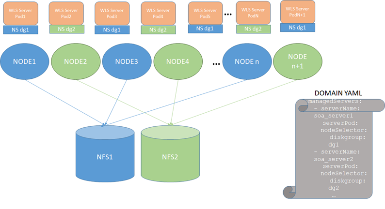
To use this configuration, follow these steps:
-
Stop the Oracle SOA Suite domain. Refer to Scripts to start and stop a domain.
-
Mount NFS1 in all even worker nodes and NFS2 in all odd worker nodes as in the diagram above. For example:
MOUNT ON ODD NODE [opc@olk8-w1 ~]$ grep "k8nfs nfs" /etc/fstab 10.10.0.21:/k8nfs /k8nfs nfs rw,relatime,vers=3,rsize=1048576,wsize=1048576,namlen=255,hard,proto=tcp,timeo=600,retrans=2,sec=sys,mountaddr=10.10.0.21,mountvers=3,mountport=2048,mountproto=udp,local_lock=none,addr=10.10.0.21 MOUNT ON EVEN NODE [opc@olk8-w2 ~]$ grep "k8nfs nfs" /etc/fstab 10.10.0.27:/k8nfs2 /k8nfs nfs rw,relatime,vers=3,rsize=1048576,wsize=1048576,namlen=255,hard,proto=tcp,timeo=600,retrans=2,sec=sys,mountaddr=10.10.0.27,mo untvers=3,mountport=2048,mountproto=udp,local_lock=none,addr=10.10.0.27 MOUNT ON ODD NODE [opc@olk8-w3 ~]$ grep "k8nfs nfs" /etc/fstab 10.10.0.21:/k8nfs /k8nfs nfs rw,relatime,vers=3,rsize=1048576,wsize=1048576,namlen=255,hard,proto=tcp,timeo=600,retrans=2,sec=sys,mountaddr=10.10.0.21,mountvers=3, mountport=2048,mountproto=udp,local_lock=none,addr=10.10.0.21 -
Copy the domain mount to an NFS replica, NFS2 (this can be done through a snapshot or through direct sftp/secure copy).
For example, if the domain is deployed in
/k8nfshosted by NFS1, after stopping the domain, secure copy the data present at/k8nfson NFS1 to/k8nfs2on NFS2:$ cd /k8nfs $ scp -R * user@[NFS2]:/k8nfs2 -
Label the odd nodes for NFS1 and the even nodes for NFS2.
For example, add the label
diskgroup=dg1for NFS1 anddiskgroup=dg2for NFS2:$ kubectl label nodes olk8-w1 diskgroup=dg1 $ kubectl label nodes olk8-w2 diskgroup=dg2 $ kubectl label nodes olk8-w3 diskgroup=dg1Verify the added labels using the following command:
$ kubectl get nodes --show-labelsSample output is:
NAME STATUS ROLES AGE VERSION LABELS olk8-m1 Ready master 10d v1.XX.X beta.kubernetes.io/arch=amd64,beta.kubernetes.io/os=linux,kubernetes.io/arch=amd64,kubernetes.io/hostname=olk8-m1,kubernetes.io/os=linux,node-role.kubernetes.io/master= olk8-m2 Ready master 10d v1.XX.X beta.kubernetes.io/arch=amd64,beta.kubernetes.io/os=linux,kubernetes.io/arch=amd64,kubernetes.io/hostname=olk8-m2,kubernetes.io/os=linux,node-role.kubernetes.io/master= olk8-m3 Ready master 10d v1.XX.X beta.kubernetes.io/arch=amd64,beta.kubernetes.io/os=linux,kubernetes.io/arch=amd64,kubernetes.io/hostname=olk8-m3,kubernetes.io/os=linux,node-role.kubernetes.io/master= olk8-w1 Ready <none> 10d v1.XX.X beta.kubernetes.io/arch=amd64,beta.kubernetes.io/os=linux,diskgroup=dg1,kubernetes.io/arch=amd64,kubernetes.io/hostname=olk8-w1,kubernetes.io/os=linux,name=admin olk8-w2 Ready <none> 10d v1.XX.X beta.kubernetes.io/arch=amd64,beta.kubernetes.io/os=linux,diskgroup=dg2,kubernetes.io/arch=amd64,kubernetes.io/hostname=olk8-w2,kubernetes.io/os=linux,name=wls1 olk8-w3 Ready <none> 10d v1.XX.X beta.kubernetes.io/arch=amd64,beta.kubernetes.io/os=linux,diskgroup=dg1,kubernetes.io/arch=amd64,kubernetes.io/hostname=olk8-w3,kubernetes.io/os=linux,name=wls2 -
To assign the appropriate selectors in the domain:
a. Edit the domain (
domain.yaml).b. Alter the managed servers section for all the managed servers configured in the cluster, sample for
soa_server1andsoa_server2as shown below:managedServers: - serverName: soa_server1 serverPod: nodeSelector: diskgroup: dg1 - serverName: soa_server2 serverPod: nodeSelector: diskgroup: dg2c. Apply the
domain.yamlchanges:$ kubectl apply -f domain.yaml
IMPORTANT: Once this redundant PV configuration is in use, all changes that reside out of the config directory in the domain will need to be copied/synced to the secondary NAS mount manually. The managed servers using NFS2 in the diagram above will replicate only configuration changes that modify files/artifacts under the
$DOMAIN_HOME/configdirectory. The rest of changes are NOT copied automatically by the WebLogic infrastructure.
For example, if you deploy an ear and specify an upload or stage directory out of the config directory, the ear files will NOT be copied by WebLogic). Fileadapter composites will place output files in mounts accessible from the pods. The mount point and PV/PVC for the different Oracle SOA Suite server file locations need to be the same, hence a different one from the one used for the $DOMAIN_HOME location.
Configure the required priority for mounts
When using block volume mounts for the Docker/CRIO images, it may occur that the mount takes time to complete on reboot. This is the case block volume with mount point being affected by network and storage latency. In this case, it is required to adjust the priority and dependency of the process on reboot, otherwise Docker will start and many images will be missing. To resolve this issue:
-
Identify the systemd units for the mounts that the container will depend on, including the NFS where the Oracle SOA Suite domain will reside. Identify mount systemd units in the Operating System:
$ cat /etc/fstab | grep "docker ext4" UUID=c07d39e4-5d8f-47af-b936-bf276cc43664 /docker ext4 defaults,_netdev,nofail 0 2 $ ls /run/systemd/generator/ | grep docker docker.mount scratch-docker.mount -
Add the units to the Docker/CRIO service as a dependency in the AFTER list. Identify mount systemd units in the operating system expand source:
$ cat /lib/systemd/system/docker.service | grep After After=network-online.target firewalld.service containerd.service docker.mount -
This guarantees that the container will start only after the required mount is ready.
Set front-end addresses
For each of the Oracle SOA Suite (soa_cluster) and Service Bus (osb_cluster) clusters, set the appropriate front-end address as follows:
-
Sign in to the WebLogic Administration Console.
-
Navigate to domain_name -> environment -> clusters.
-
Click the cluster name.
-
Click the HTTP tab.
-
Enter the Frontend Host and Frontend Port details.
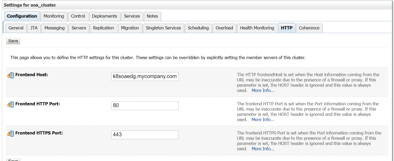
Note: Set the front-end details for each cluster and for the Administration Server.
Enable FAN for GridLink data sources
Data sources in the default deployment for Oracle SOA Suite on Kubernetes use generic data sources. With ONS auto-registration in 12.2 Database and later, it is only necessary to enable FAN for the data sources to convert to GridLink (GLDS). You can do this by using the WebLogic Administration Console or the following command and restarting the Administration Server and the managed servers:
grep -L fan-enabled $domain_home/config/jdbc/*.xml | xargs sed -i "s/<\/jdbc-data-source>/<jdbc-oracle-params><fan-enabled>true<\/fan-enabled><\/jdbc-oracle-params><\/jdbc-data-source>/g"
After the change is applied, verify that all data sources are marked as GridLink Data Sources in the WebLogic Administration Console.
Configure ASM
Refer to the on-premises Enterprise Deployment Guide for steps to configure Automatic Service Migration.
Configure coredns allocation
NOTE: This step is applicable to any Kubernetes system using
corednsregardless of Oracle SOA Suite deployment. However, the worker node creation is implicit in the setup, hence it is applied in this context (post Oracle SOA Suite deployment).
Configure replicas for cordens to spawn both control plane and master plane. If a restore operation is performed on the control plane, worker nodes may stop working properly. If the coredns lands entirely in the worker nodes, the control plane may not function correctly if they are brought down for maintenance. Place at least two coredns pods on the control plane and another two on the worker nodes. The coredns footprint is low.
 VIRT    RES    SHR S  %CPU %MEM     TIME+ COMMAND

146268  41684  29088 S   0.3  0.1  25:44.04 coredns
According to the CoreDNS documentation, you can estimate the amount of memory required for a CoreDNS instance (using default settings) with the following formula:
MB required (default settings) = (Pods + Services) / 1000 + 54
Hence, first label nodes in both control and worker plane.
$ kubectl label nodes olk8-m1 area=dnsarea
$ kubectl label nodes olk8-m2 area=dnsarea
$ kubectl label nodes olk8-m3 area=dnsarea
$ kubectl label nodes olk8-w1 area=dnsarea
$ kubectl label nodes olk8-w2 area=dnsarea
$ kubectl label nodes olk8-w3 area=dnsarea
And then update the coredns deployment to use topology spread constraints
NOTE: Topology spread constraints is beta starting in Kubernetes v1.18
First, enable the feature gate in kube-api server and in kube-scheduler. Then, modify the coredns deployment for an appropriate spread of pods across worker and control plane nodes.
The coredns topology spread config details are:
Click below for sample updated coredns deployment:
The labels and spread topology changes are:
  labels:
        foo: bar
        k8s-app: kube-dns
  topologySpreadConstraints:
  - labelSelector:
      matchLabels:
        foo: bar
    maxSkew: 1
    topologyKey: area
    whenUnsatisfiable: DoNotSchedule
This guarantees an even distribution across the master and worker nodes, so that if the control plane is restored, the worker pods will continue without issues and the other way around.
Sample resulting coredns distribution:
$ kubectl get pods -A -o wide | grep coredns
kube-system   coredns-84b49c57fd-4fz4g                         1/1     Running     0          166m    10.244.1.20   olk8-m2   <none>           <none>
kube-system   coredns-84b49c57fd-5mrkw                         1/1     Running     0          165m    10.244.4.76   olk8-w2   <none>           <none>
kube-system   coredns-84b49c57fd-5zm88                         1/1     Running     0          165m    10.244.2.17   olk8-m3   <none>           <none>
kube-system   coredns-84b49c57fd-nqlwb                         1/1     Running     0          166m    10.244.4.75   olk8-w2   <none>           <none>
Adjust server’s pods Liveness Probe
By default, the liveness probe is configured to check liveness every 45 seconds, which might cause requests to be routed to backend pods that are no longer available during outage scenarios. Recommended to adjust liveness probe values so that on hard node failures pods are marked as down faster. To configure a more aggressive probe, edit the domain and change the serverPods.livenessProbe values to the following:
livenessProbe:
   failureThreshold: 1
   initialDelaySeconds: 30
   periodSeconds: 5
   successThreshold: 1
   timeoutSeconds: 3
Refer WebLogic Kubernetes Operator documentation for details on how to customize the liveness probe.