Create the WebLogic Deploy Tooling model
The WebLogic Deploy Tooling project provides a set of single-purpose tools for performing lifecycle operations of WebLogic Server domains. These tools work off a model of the domain. The model contains three types of files:
- Model file – A YAML description of the domain that is aligned with WebLogic Scripting Tool (WLST) offline folders and attributes.
- Variables file – An optional Java properties file that contains key/value pairs where the key matches with a token placed in the model file.
- Archive file – An optional ZIP file that contains any file artifacts that need to exist in the domain, for example, a WAR file that contains the binaries for a Web application.
For more detailed WDT information, see the WebLogic Deploy Tooling documentation .
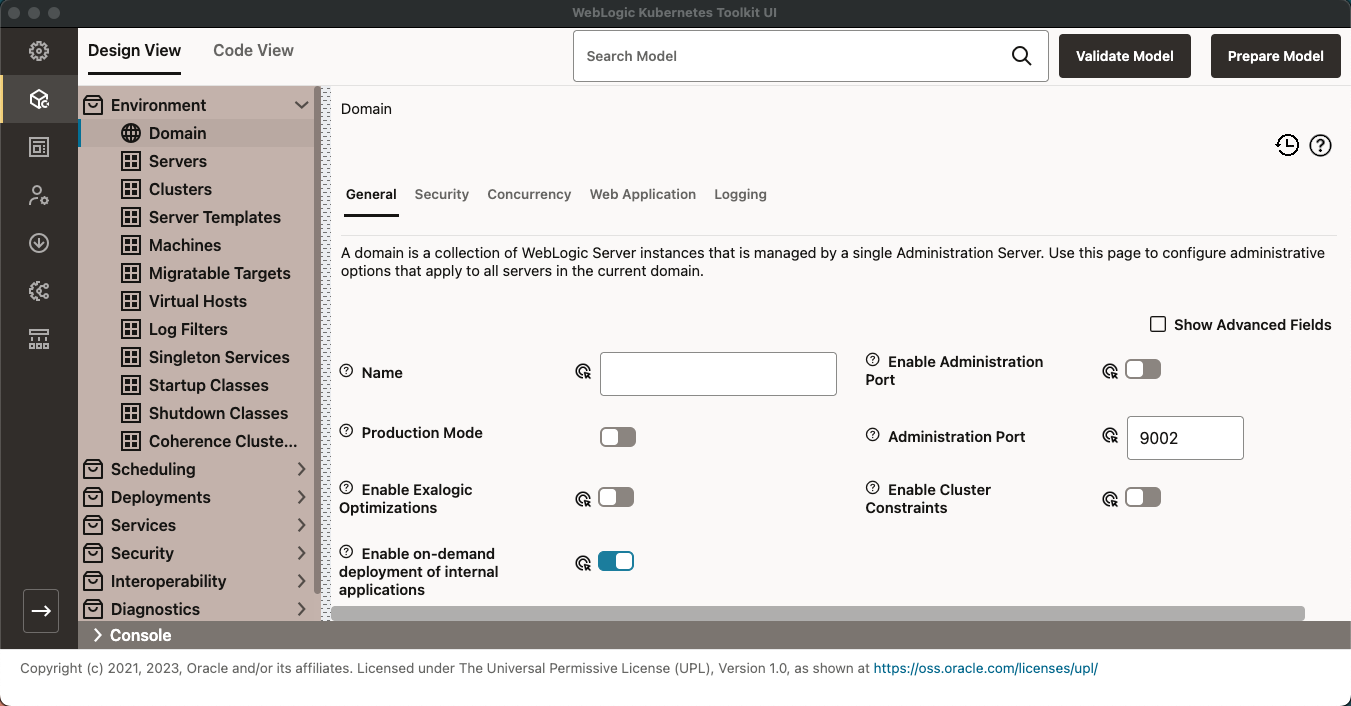
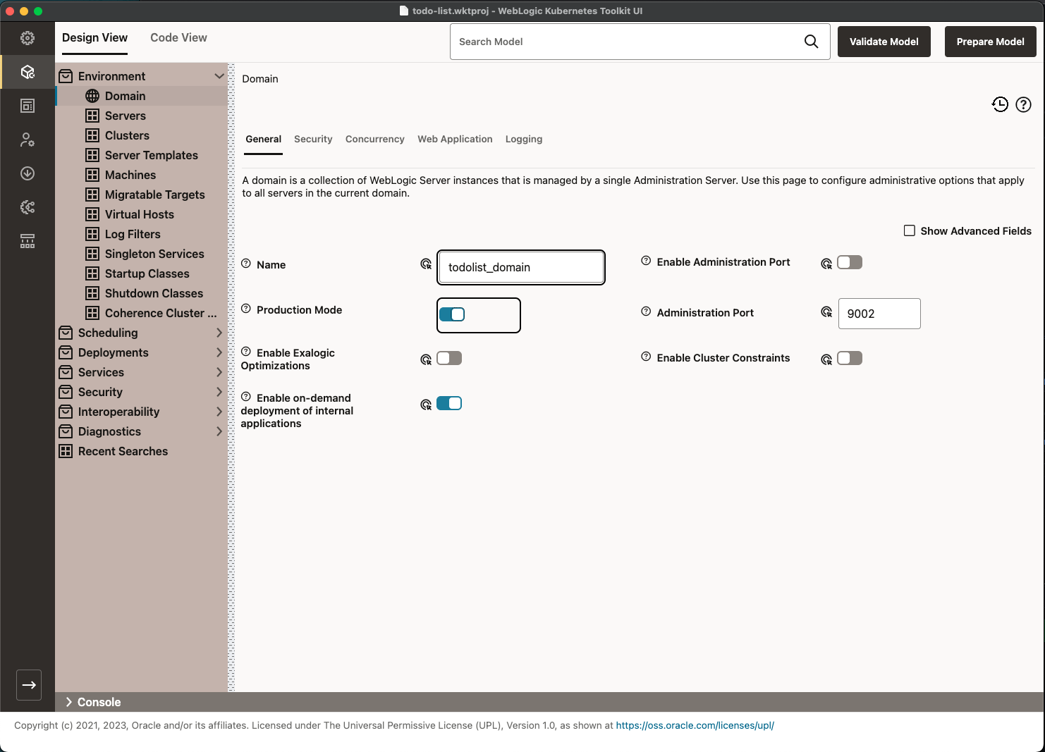
WKT UI provides tooling to make it easy for you to create and edit a WDT model. This image shows the Design View tab
of the Model page. It allows visual editing of a model.
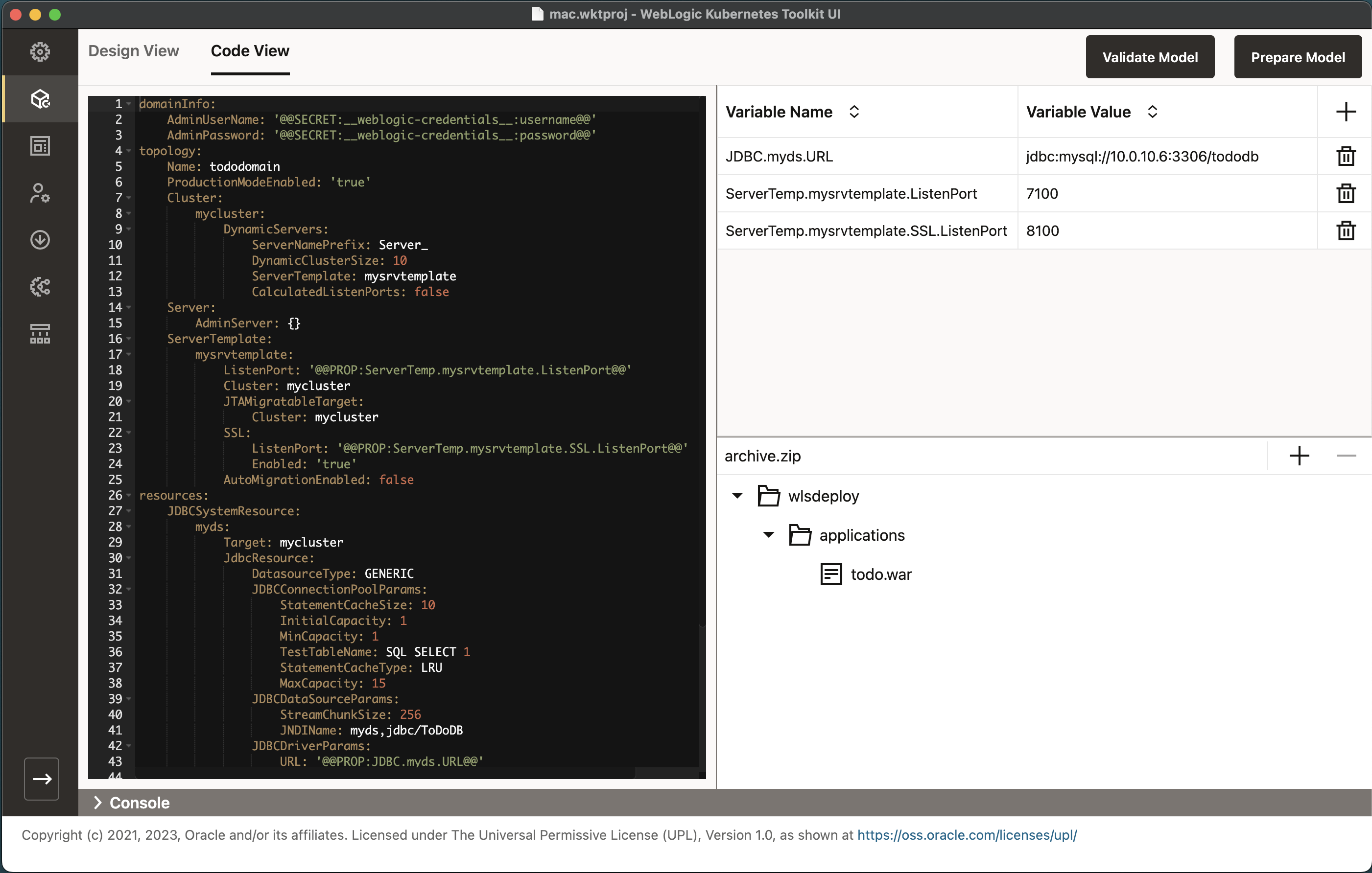
The following image shows the Code View tab of the Model page. It lets you directly edit each of the three different file
types that make up the model. In the center of the screen, you’ll find the YAML editor for the model file. On the right,
you’ll find the variables file editor and the archive file editor. At this point, all the sections are blank.
WKT UI also supports discovering an existing domain to extract the model for that domain. It accomplishes this by using
the WDT
Discover Domain
tool. To use this
functionality, go to File > Add Model and choose either:
Discover Model (offline)– With this option, WDT reads the domain directory from the local file system to extract the model files.Discover Model (online)– With this option, WDT connects to the domain’s running Administration Server to extract the model files. To collect all of the archive file contents automatically, the domain must be running on the local machine so that WDT has access to the domain’s file system.
If you want to collect the model from a domain running on another machine, you can use the Remote Discovery option. With this option, at the end of the Discover Domain (online) action, WDT will tell you which files you need to collect and add to the archive file. See Online Remote Discovery .
Because the ToDo List application has minimal requirements from the domain, you will create the model by hand. If you would prefer to create a local domain and use the discover model functionality, see Create ToDo List Domain in the Advanced section.
Create the ToDo List Domain
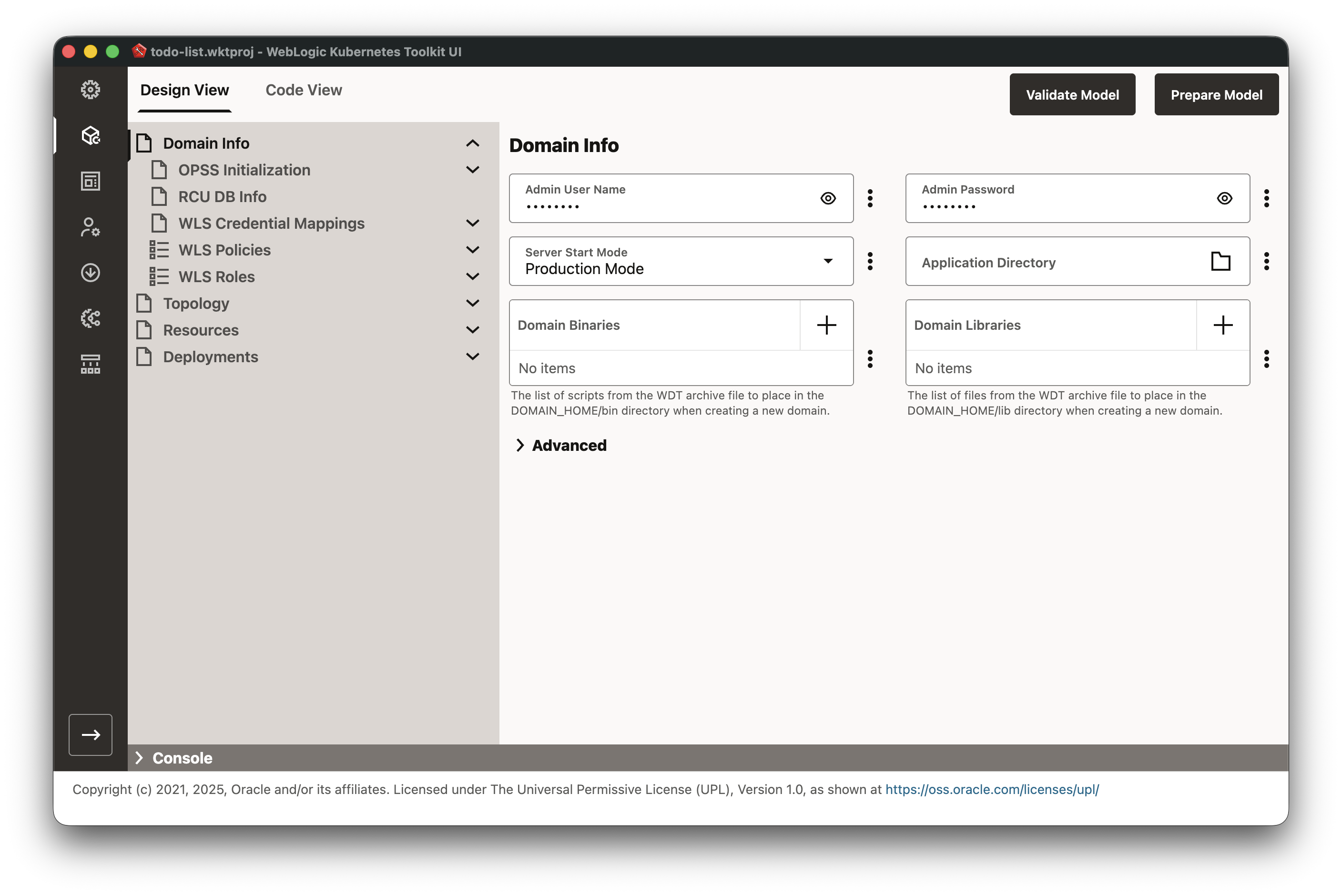
Start on the Model - Design View tab, which will default to the Domain Info section top-level page. Set the
Admin User Name and Admin Password fields to the user name and password that you want for your WebLogic domain. Also,
select the Server Start Mode value of Production Mode to simplify things for this guide.
Next, click on the Topology section in the navigation bar to go to the domain settings. Enter todolist_domain in
the Name field. There is no need to turn on Production Mode Enabled since you already took care of that on the
Domain Info page.
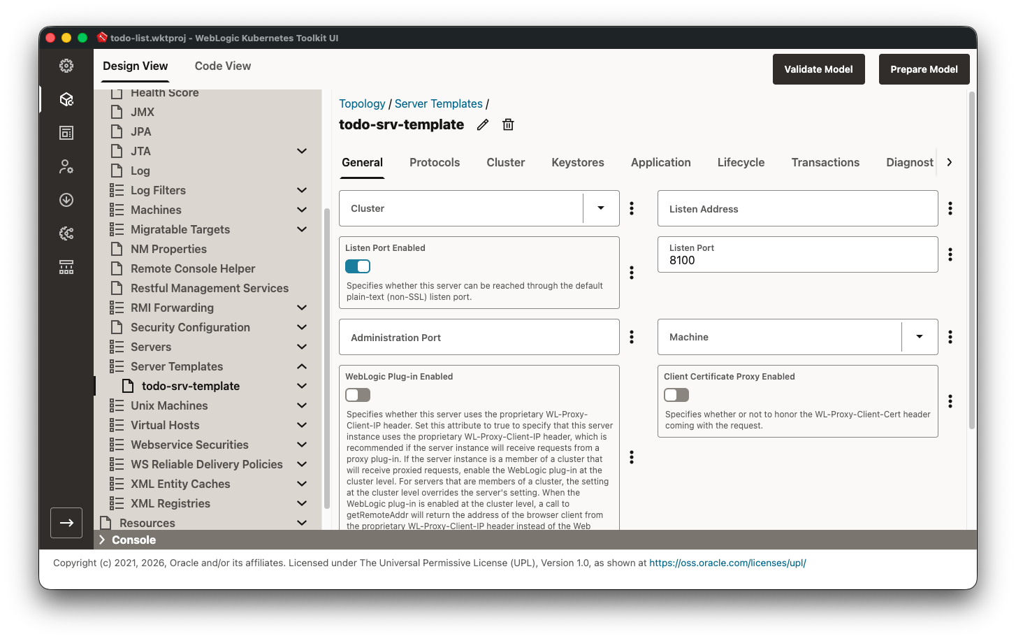
Next, you need to create a server template that you will use with your dynamic cluster. Select the Server Templates
element, add a new server template using the + icon in the table header, specify the name as todo-srv-template,
and then click OK.
After you create the template, select the link in the table, enable Listen Port Enabled and
set the Listen Port to 8100 so that the screen looks like the following image.
Next, you will need to create the dynamic cluster. Select the Clusters item in the navigation bar and create a new
cluster named mycluster. Before moving on to configure the new cluster, return to the Server Template todo-srv-template
page and set the Cluster field using the dropdown menu to mycluster.
Navigate to the new cluster, Cluster > mycluster, and select the Dynamic Servers folder under mycluster in the navigation bar. Set the fields to the values specified in the following table. A couple of things to note:
- The
Max Dynamic Cluster Sizeis in the WLDF Elasticity Framework Settings expandable section at the bottom of the page. - Although the
Enabled Calculated Listen Portsfield is already in thefalseposition (because it is not in the model yet), the default value istrue. As such, you must turn the switch on to add it to the model and then off so that the model value is set tofalse. You might wonder how to remove it from the model if you added it by mistake. Simply use the three dot menu (also known as the kebab menu) to the right of the control and select theRemove the field from the modelradio button and select OK.
| Field Name | Value |
|---|---|
Server Template |
todo-srv-template |
Server Name Prefix |
ToDoServer- |
Dynamic Cluster Size |
10 |
Max Dynamic Cluster Size |
10 |
Enable Calculated Listen Ports |
Off |
Create a Data Source
The next step is to create a data source to communicate with the MySQL database. Before doing that, switch to the
Code View tab to see what the WDT model looks like so far.
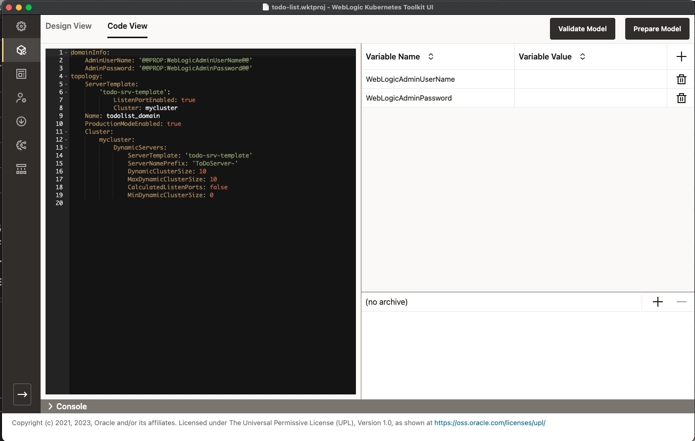
As you can see in the preceding image, the settings you entered are represented in the YAML Editor. Now, switch back to
the Design View tab.
Go to the Resources > Data Sources section, add a new Data Source using the values in the following table, and then click Create. Note that you can choose any database user name and password below. Just make sure that you use these same credentials when deploying the MySQL database later.
| Field Name | Value |
|---|---|
Name |
myDataSource |
Datasource Type |
Generic Data Source |
Targets |
mycluster |
Driver Name |
com.mysql.cj.jdbc.Driver |
URL |
jdbc:mysql://mysql:3306/tododb |
Password |
Choose a database password for the database user |
Database User Name |
Create Property named user with the database user name as its value |
Global Transactions Protocol |
OnePhaseCommit |
JNDI Names |
jdbc/ToDoDB |
After the myDataSource Data Source is created, go to the JDBC Connection Pool Parameters folder (underneath the
myDataSource in the navigation bar) > Connection Testing tab and make the following changes:
- Enable
Test Connection On Reserve. - Set the Test Table Name to
ToDos.
Now, you need to add the application. Go to Deployments > Applications section, add a new application using the
values in the following table, and then click Create. You must replace the $QS_HOME value in the table with the
path where you stored the Quick Start directory when downloading the code.
When selecting the application to use, make sure to select the proper application based on the target WebLogic Server version you intend to use. Choose based on the following:
$QS_HOME/app/target/todo.war: Choose this todo.war file for WebLogic Server versions 14.1.1.0 or 14.1.2.0$QS_HOME/app-jakarta/target/todo.war: Choose this todo.war for WebLogic Server version 15.1.1.0 or newer
Note that while the sample application can run on WebLogic Server 12.2.1.4, you will need to change the
$QS_HOME/app/src/main/webapp/WEB-INF/web.xml deployment descriptor to point to the Java EE 7 Web Application 3.1
specification and rebuild the binary by running mvn clean package in the $QS_HOME/app directory.
When selecting the Source Path using the file chooser, make sure to choose the Add this file to the archive file option
on the Source Path Location dialog that follows the file chooser. Note that after doing this, the Source Path value
will change to reflect its path in the archive file (wlsdeploy/applications/todo.war).
| Field Name | Value |
|---|---|
Name |
todo |
Source Path |
$QS_HOME/app/target/todo.war or $QS_HOME/app-jakarta/target/todo.war |
Targets |
mycluster |
Even though the model is complete enough to create a local domain, you still need to add a few things so that the WebLogic Kubernetes Operator can use the model.
- Create a new Server called
AdminServerwithout changing any of its attributes. - On the Topology page, set the
Admin Server Namefield toAdminServer.
Once you have done this, switch back to the Code View tab and your topology section of the model should look like
the following. Do not worry if the fields or sections are in different orders.
Validate and Prepare the Model
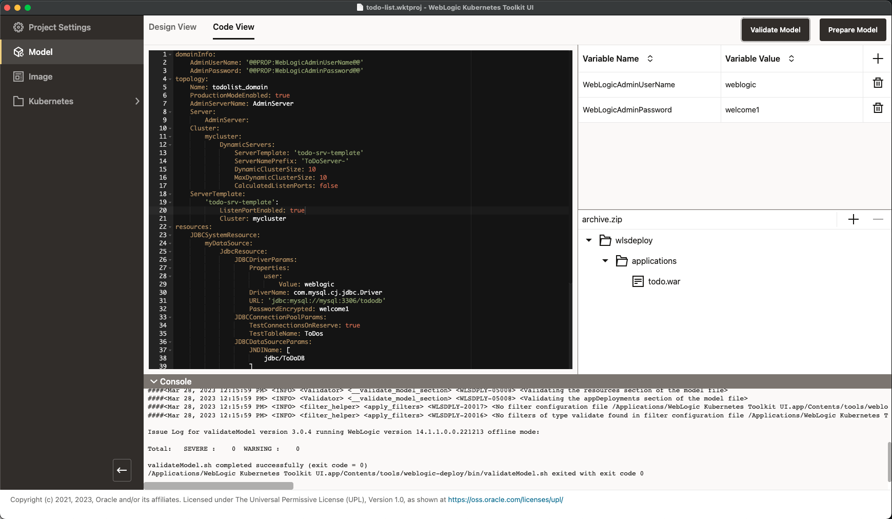
The domain model is now complete. Go ahead and validate the model by clicking Validate Model or using the Go menu,
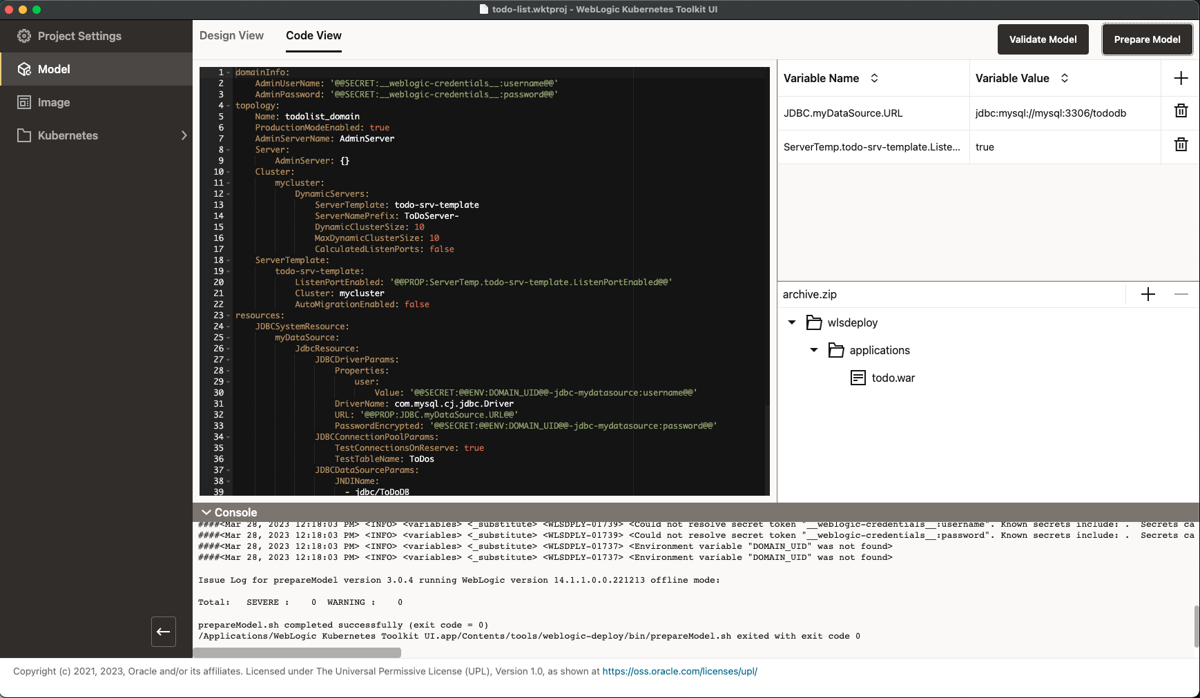
Validate Model Files menu item. Doing this will invoke the WDT Validate Model Tool and the Console window at the
bottom of the screen will display the output of the tool, as shown in the following image. You can close the Console
Window at any time.
When deploying a domain in Kubernetes, you need to prepare it for that environment. The WDT Prepare Model Tool gives you what you need to accomplish that. WKT UI has a special integration with Prepare Model in that not only does it adjust the model for the Kubernetes environment, but also it returns data extracted from the model that WKT UI needs. For example, Prepare Model returns the list of WebLogic clusters and non-clustered managed servers that other parts of the application use to tailor the environment for this domain.
Click Prepare Model to invoke the WDT Prepare Model Tool. Because you chose to use Model-in-Image for the Quick Start exercise, Prepare Model made several changes to your model:
- Replaced credentials with tokens that reference Kubernetes Secrets.
- Replaced fields like the
Data Source URLwith a token that references a variable.
Make sure you save the project before you move to the next section.
The following image shows the completed model that is ready to put in an image.